Injection Molding With High Heat Resins
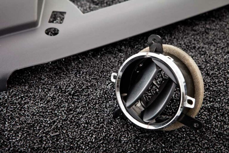
Temperature plays a huge role in the custom injection molding process– even helping to determine the type of resin the part is made from. Resins

By the time a 3D model lands on your molder’s desk, most of the part’s cost has already been decided. Design for manufacturing injection molding is the structured review work that closes the gap between a working prototype and a tool that can run reliably at production volume. Done well, it surfaces the geometry, material, and process decisions that should be settled before anyone cuts steel.
Design for manufacturing for injection molding is the engineering process of optimizing a part’s geometry, material, and process inputs for a specific molding production environment before a tool is built. It treats the part design and the mold design as one integrated problem rather than two sequential ones. The goal is not just a part that can be molded. It is a part that can be molded consistently, at the cycle time and quality level the program requires.
That distinction matters. A prototype proves the part works. DFM proves the part will keep working across thousands or millions of shots. A structured DFM approach reduces risk and minimizes late-stage surprises by aligning part intent with molding realities before tool design begins.
DFM is closely related to design for assembly (DFA), but the two are not interchangeable. DFA focuses on how individual parts fit and join together. DFM focuses on how each individual part can be manufactured efficiently. On most injection molding programs, DFM comes first because part geometry has to be moldable before assembly tradeoffs can be evaluated.
DFM happens before tooling because the cost and time impact of design changes climbs sharply once steel is cut. A wall-thickness revision in CAD is a redraw. The same revision after a mold has been machined can mean welding, re-cutting, or building a new tool. Peer-reviewed manufacturing research estimates that 70% to 80% of total product cost is determined during the early design phase of product development, which makes early design review one of the highest-leverage activities on the program.
The practical version of that math looks like this:
None of this means DFM has to be slow. It means the review needs to happen at the stage where decisions are still reversible. The strongest indicator of a healthy DFM process is that all six decisions covered below are settled in CAD, with the molder’s engineering team aligned, before tool design begins. For how those early decisions translate to per-part economics, see what drives the cost of custom injection molding.
A complete DFM review for an injection molded part touches dozens of inputs, but six decisions carry the most weight. Each one is recoverable in CAD and expensive to revisit after tooling. Treat them as the checklist for the design review with your molder’s engineering services team, and resolve all six before the tool design is locked.
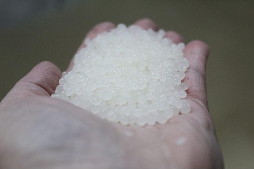
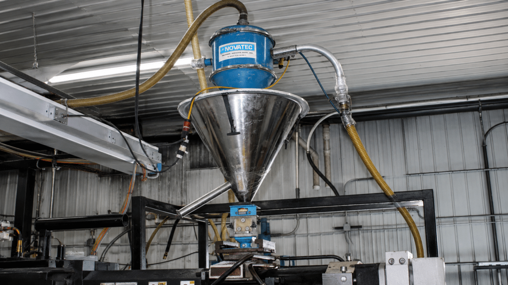
Material selection is the first DFM decision because every downstream geometry choice depends on it. Resin shrinkage, flow behavior, glass-transition temperature, and chemical resistance all set the boundaries for what the part can look like and how it will run on the press.
Three questions drive the conversation:
Pioneer Plastics’ engineering team treats material selection as a joint decision rather than a customer specification. The customer brings the performance requirements. The molder brings the processing reality. For a deeper look at how resin choice shapes part design, see the post on injection molding materials.
Wall thickness and rib strategy is the second DFM decision because it determines whether the part will fill and cool predictably. Uniform walls minimize warp and sink. Strategic ribbing adds stiffness without adding mass. Both choices interact with the chosen resin and with the gating decisions that come next.
This post will not duplicate the wall-thickness ranges and rib geometry ratios already published on the Pioneer Plastics blog. For specific dimensional guidance, see the post on designing custom plastic parts for fit and function, which covers wall thickness, draft, and ribbing rules in detail.
At the DFM review, the questions to settle are:
Skipping this conversation is one of the most common drivers of downstream defects. Sink, warp, voids, and short shots usually trace back to wall and rib decisions that were never reviewed together. See common injection molding defects and how to avoid them for how poor wall and rib choices show up in molded parts.
Draft and parting line decisions determine how the part comes out of the mold and where the visible tool-split line will fall on the finished surface. Insufficient draft causes drag marks, ejection stress, and stuck parts. A poorly placed parting line shows up as a visible witness on a finished surface a customer can see.
During the DFM review, three items need explicit agreement between the customer’s design engineer and the molder:
If the part has features that pull through the parting line, including undercuts, side holes, snap fits, or threads, those geometries need to be flagged here. They affect every subsequent decision. The Pioneer Plastics post on complex injection molded part design walks through how undercuts, living hinges, and other features that cross the parting line are typically handled in production tooling.
Gate location and runner system is the fourth DFM decision and the one customers most often defer to the molder. Gate placement controls where molten plastic enters the cavity, how it flows, and where weld lines, vestiges, and cosmetic blemishes will appear. The runner system, hot or cold, determines material yield and cycle time.
Four questions drive the gating conversation:
This is where having the molder’s engineering team in the room early pays off. Customers can specify the cosmetic surface; the molder’s team translates that constraint into a gate strategy. Doing it the other way around, by locking gate locations without consulting the molder, is one of the most common reasons DFM reviews end up restarting late in the project.
Ejection strategy and side-action requirements determine how the finished part is removed from the cavity and what additional mold motion is needed to release features that cannot pull straight in the primary direction. These decisions drive tool complexity, cycle time, and ongoing maintenance cost more than almost any other input.
Settle the ejection plan against three specific questions:
The conversation here is often where Pioneer Plastics’ tool development and management experience adds the most value. The team has built and maintained tools across decades of production programs, which means slide and lifter decisions are made with the full lifecycle of the mold in mind, not just the first hundred shots.
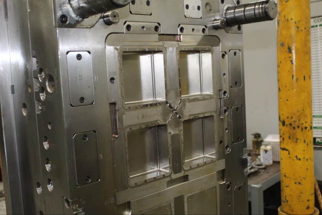
Cavitation and shot-size planning is the sixth DFM decision and the bridge between part design and production planning. The number of cavities in the tool, paired with the press tonnage and shot size, determines whether the program economics work. This decision sits at the intersection of part geometry, projected volume, and equipment availability.
Three inputs drive the decision:
Single-cavity, multi-cavity, and family molds each carry tradeoffs around tooling cost, per-part cost, and quality consistency. For a closer look at how that decision plays out in practice, see the post on single-cavity, multi-cavity, and family mold options. For programs that are transitioning out of prototyping into production tooling, the related discussion of prototype and production injection molding covers how the cavitation conversation differs at each stage.
DFM collaboration is the back-and-forth review process between the customer’s design engineer and the molder’s in-house engineering team that resolves the six decisions above before tool design begins. It is not a single meeting or a one-way document handoff. It is an iterative conversation, usually compressed into one to three weeks, that turns a working prototype into a production-ready CAD package.
A productive DFM engagement typically includes:
Pioneer Plastics’ engineering services team brings 175+ years of combined engineering and mold-making experience to that review. The team works as an extension of the customer’s design engineering group, not as a vendor receiving specifications. That collaboration model is what the formal DFM process is designed to enable.
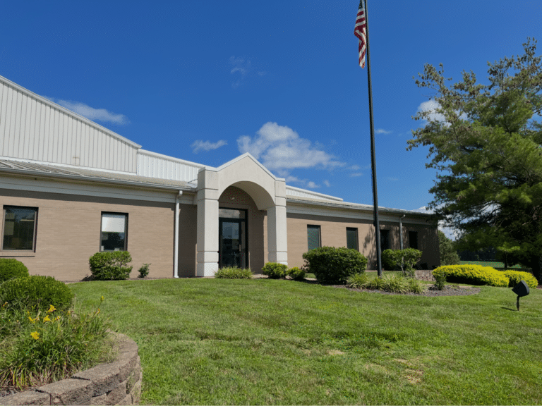
It is also an argument for domestic manufacturing on programs where time-zone-aligned engineering matters. 244,000 U.S. manufacturing jobs were announced in 2024 via reshoring and foreign direct investment, continuing a multi-year reshoring trend. For OEMs evaluating where to build a new tool, the ability to sit in the same room or on the same call with the molder’s engineering team during DFM is part of what reshoring is buying.
DFM in plastic injection molding is the engineering review process that aligns a part’s geometry, material, and process choices with what an injection mold can reliably produce at production volume. It happens before tool design begins. The review typically covers six early decisions: material selection, wall thickness and rib strategy, draft and parting line, gate location and runner system, ejection and side-action requirements, and cavitation and shot-size planning.
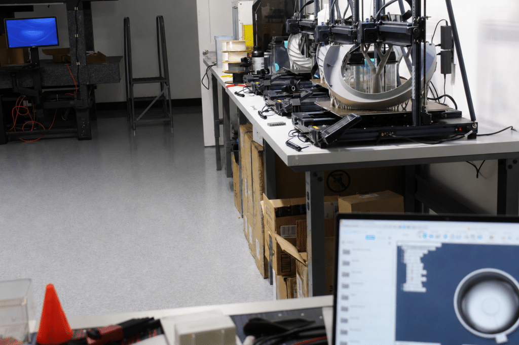
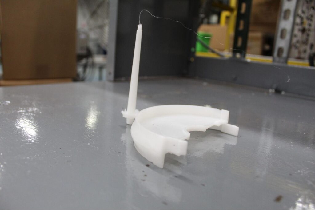
DFM should start as soon as the part design is past the rough prototyping stage and before the customer commits to a production tool. If the part is being printed on a 3D printer for prototyping, the DFM review can begin in parallel with prototype iteration. The goal is to involve the molder’s engineering team early enough that geometry, material, and process decisions are still reversible in CAD.
Responsibility for DFM is shared, but the work is led by the molder’s engineering team because they own the manufacturing process. The OEM’s design engineer brings the part’s functional requirements, performance targets, and cosmetic specifications. The molder brings the processing knowledge, tooling experience, and equipment constraints. A productive DFM review treats both inputs as equally authoritative and resolves disagreements through iteration, not handoff.
Skipping DFM and going straight to tooling almost always costs more time and money than the DFM review itself would have. Common outcomes include parts that fill inconsistently, cosmetic defects on visible surfaces, ejection problems, premature tool wear, and full mold rework once a sample shot reveals what the CAD review would have caught. Because most of total product cost is determined during the early design phase, the savings from skipping DFM are usually borrowed from a much larger downstream bill.
DFM optimizes how an individual part is manufactured. DFA optimizes how multiple parts fit and join together in a finished product. For injection molded parts, DFM typically comes first because part geometry has to be moldable before assembly tradeoffs can be evaluated. On programs with complex assemblies, the two disciplines overlap and are often reviewed together, but they answer different questions and use different tools.
Design for manufacturing is most valuable when it starts before the first quote, not after the first mold. If you have a part in development and want a structured review against the six early decisions covered above, request a quote from Pioneer Plastics and get the engineering team involved while changes are still reversible. The earlier the conversation starts, the more leverage you have on cost, quality, and lead time.
Temperature plays a huge role in the custom injection molding process– even helping to determine the type of resin the part is made from. Resins

In today’s dynamic manufacturing world, finding a production method that is both efficient and adaptable is crucial for meeting unique customer demands. Custom injection molding
“Made in USA” manufacturing signifies far more than a simple label—it represents a commitment to quality, local economic growth, and ethical production practices. At its